Features and Benefits
- 3-Axis – Fx Fy Fz; independent bridges
- 2N to 50N force range
- Compact size
- Low crosstalk
- IP65 Rating
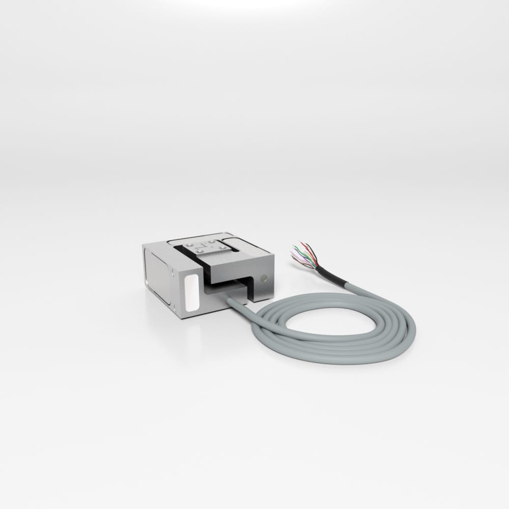
3A40 3-Axis Load Cell

The pricing listed on our website is only for U.S. buyers and all pricing is subject to change without notice. Any inquiries for products from buyers outside of the U.S. will receive a quote and availability from the licensed distributor nearest your region. These prices will be based on product availability, currency conversions, markets, taxes, shipping costs, as well as local support.

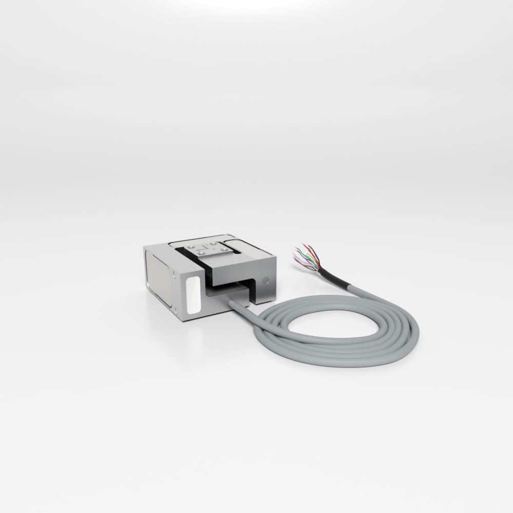
Model 3A40 has 3 independent axes in a small package size. Capacities available are 2N, 10N, 20N, and 50N. Product is made from aluminum alloy so it is very light weight.
Interface’s 3A40 3-axis load cell measures forces simultaneously in 3 mutually perpendicular axes: X, Y, and Z – positive and negative. Each axis provides a unique mV/V output and requires no mathematical manipulation. The 3-axis load cell is built to minimize eccentric loading effects and crosstalk between axes.
The 3A40 is ideally suited to many industrial and scientific applications, such as aerospace, robotics, automotive and medical research (orthopedics and bio-mechanical). The load cell is provided in various capacity ranges and sizes with each of the three axes providing the same capacity.
We are happy to work with your design needs – providing a custom design if warranted for varying capacities (between X, Y, and Z), higher temperature capability, or OEM/private labeling if needed.
Model 3A40 has 3 independent axes in a small package size. Capacities available are 2N, 10N, 20N, and 50N. Product is made from aluminum alloy so it is very light weight.
| ACCURACY – (MAX ERROR*) | ||
| Nonlinearity – %FS | ±0.2 | |
| Hysteresis – %FS | ±0.5 | |
| Creep, in 30 min – % | ±0.05 | |
| TEMPERATURE | ||
| Effect on Zero – %RO / deg | °C | ±0.05 |
| Effect on Output – % / def | °C | ±0.05 |
| Operating Range | °C | -20 to +70 |
| °F | -4 to +185 | |
| ELECTRICAL | ||
| Rated Output (Nominal) – mV/V | 0.5 | |
| Max. Excitation Voltage – V | 10 | |
| Zero Balance – mV/V | <0.1 | |
| Input Resistance, x, y, & z axis – Ω | 350 | |
| Output Resistance, x, y, & z axis – Ω | 350 | |
| MECHANICAL | ||
| Rated Capacity (FS) | N | ±2,±10, ±20, ±50 |
| lbf | ±2,±10, ±20, ±50 | |
| Cable length | m | 3 |
| ft | 9.8 | |
| Material | Aluminum Alloy | |
| Total Weight | g | 85 |
| lbs | 0.18 | |
| Safe Overload – %CAP | 150 | |
| Ultimate Overload – %RO | 300 | |
| Dimensions | 40 mm x 40mm x 20mm | |
| Standard Connector | 37-pin D-sub | |
| ECCENTRICITY AND MOMENT* | ||
| x into y - %FS | 0.5 | |
| y into x - %FS | 0.5 | |
| z into x - %FS | 1 | |
| z into y - %FS | 1 | |
| x into z - %FS | 1 | |
| y into z - %FS | 1 | |
| Influence of Eccentric load %FS/2Nm | 0.5 | |
| Capacity | 2N | 10N | 20N | 50N |
| Fx (N) | 2 | 10 | 20 | 50 |
| Fy (N) | 2 | 10 | 20 | 50 |
| Fz (N) | 2 | 10 | 20 | 50 |
| Max Bending Moment (Nm) | 5 | 5 | 5 | 5 |
| Torque Limit (Nm) | 5 | 5 | 5 | 5 |
| Breaking Force %FS | 600 | 600 | 600 | 600 |
| Material | Aluminium | |||
| Protection (IP) | 65 | |||
U.S. dimensions and capacities are provided for conversion only. Standard products have International System of Units (SI) capacities and dimensions.
| Description | Wire Color | 37-Pin D-Sub | 16-Pin M23 | |
| Shield | Shield | Shield | 1 | N/C |
| X-Axis | + Excitation | Brown | 20 | 2 |
| - Excitation | White | 27 | 1 | |
| + Output | Green | 22 | 3 | |
| - Output | Yellow | 25 | 4 | |
| Y-Axis | + Excitation | Pink | 2 | 6 |
| - Excitation | Gray | 9 | 5 | |
| + Output | Blue | 4 | 7 | |
| - Output | Red | 7 | 8 | |
| Z-Axis | + Excitation | Purple | 11 | 10 |
| - Excitation | Black | 18 | 9 | |
| + Output | Gray/Pink | 13 | 11 | |
| - Output | Red/Blue | 16 | 12 |
| Dimensions | 40.00 × 40.00 × 20.00 in |
|---|
| ACCURACY – (MAX ERROR*) | ||
| Nonlinearity – %FS | ±0.2 | |
| Hysteresis – %FS | ±0.5 | |
| Creep, in 30 min – % | ±0.05 | |
| TEMPERATURE | ||
| Effect on Zero – %RO / deg | °C | ±0.05 |
| Effect on Output – % / def | °C | ±0.05 |
| Operating Range | °C | -20 to +70 |
| °F | -4 to +185 | |
| ELECTRICAL | ||
| Rated Output (Nominal) – mV/V | 0.5 | |
| Max. Excitation Voltage – V | 10 | |
| Zero Balance – mV/V | <0.1 | |
| Input Resistance, x, y, & z axis – Ω | 350 | |
| Output Resistance, x, y, & z axis – Ω | 350 | |
| MECHANICAL | ||
| Rated Capacity (FS) | N | ±2,±10, ±20, ±50 |
| lbf | ±2,±10, ±20, ±50 | |
| Cable length | m | 3 |
| ft | 9.8 | |
| Material | Aluminum Alloy | |
| Total Weight | g | 85 |
| lbs | 0.18 | |
| Safe Overload – %CAP | 150 | |
| Ultimate Overload – %RO | 300 | |
| Dimensions | 40 mm x 40mm x 20mm | |
| Standard Connector | 37-pin D-sub | |
| ECCENTRICITY AND MOMENT* | ||
| x into y - %FS | 0.5 | |
| y into x - %FS | 0.5 | |
| z into x - %FS | 1 | |
| z into y - %FS | 1 | |
| x into z - %FS | 1 | |
| y into z - %FS | 1 | |
| Influence of Eccentric load %FS/2Nm | 0.5 | |
| Capacity | 2N | 10N | 20N | 50N |
| Fx (N) | 2 | 10 | 20 | 50 |
| Fy (N) | 2 | 10 | 20 | 50 |
| Fz (N) | 2 | 10 | 20 | 50 |
| Max Bending Moment (Nm) | 5 | 5 | 5 | 5 |
| Torque Limit (Nm) | 5 | 5 | 5 | 5 |
| Breaking Force %FS | 600 | 600 | 600 | 600 |
| Material | Aluminium | |||
| Protection (IP) | 65 | |||
U.S. dimensions and capacities are provided for conversion only. Standard products have International System of Units (SI) capacities and dimensions.
| Description | Wire Color | 37-Pin D-Sub | 16-Pin M23 | |
| Shield | Shield | Shield | 1 | N/C |
| X-Axis | + Excitation | Brown | 20 | 2 |
| - Excitation | White | 27 | 1 | |
| + Output | Green | 22 | 3 | |
| - Output | Yellow | 25 | 4 | |
| Y-Axis | + Excitation | Pink | 2 | 6 |
| - Excitation | Gray | 9 | 5 | |
| + Output | Blue | 4 | 7 | |
| - Output | Red | 7 | 8 | |
| Z-Axis | + Excitation | Purple | 11 | 10 |
| - Excitation | Black | 18 | 9 | |
| + Output | Gray/Pink | 13 | 11 | |
| - Output | Red/Blue | 16 | 12 |
| Dimensions | 40.00 × 40.00 × 20.00 in |
|---|
| Short Description | Sku | Price |
|---|---|---|
| Model 3A40 3-Axis Load Cell, 10N Capacity | 3A40- 10N | $2,575.00 |
| Model 3A40 3-Axis Load Cell, 20N Capacity | 3A40-20N | $2,575.00 |
| Model 3A40 3-Axis Load Cell, 2N Capacity | 3A40-2N | $2,700.00 |
| Model 3A40 3-Axis Load Cell, 50N Capacity | 3A40-50N | $2,575.00 |
| Model 3A40 3-Axis Load Cell, 10N Capacity | 3A40-10N-D11 | $2,565.00 |
| Model 3A40 3-Axis Load Cell, 20N Capacity | 3A40-20N-D11 | $2,565.00 |
| Model 3A40 3-Axis Load Cell, 2N Capacity | 3A40-2N-D11 | $2,685.00 |
| Model 3A40 3-Axis Load Cell, 50N Capacity | 3A40-50N-D11 | $2,565.00 |


 WSSB Welded Stainless Steel IP68 Environment Protected S-Beam