Features and Benefits
- Ultra-fast update rate of 2000 per second
- Wireless range up to 800 m (2,625 ft)
- Low power mode for long battery life
- Free Visualization software
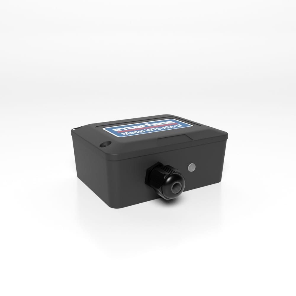
WTS-AM-1F Wireless Fast Strain Bridge Transmitter Module
The pricing listed on our website is only for U.S. buyers and all pricing is subject to change without notice. Any inquiries for products from buyers outside of the U.S. will receive a quote and availability from the licensed distributor nearest your region. These prices will be based on product availability, currency conversions, markets, taxes, shipping costs, as well as local support.

WTS-AM-1F Wireless Fast Strain Bridge Transmitter Module connects to strain bridge transducers such as load cells, torque sensors, strain gauges and pressure modules and forms part of the WTS modular telemetry system that have up to 3.1 mV/V output max. The data transmitted by the WTS-AM-1F can be received by multiple WTS receivers that include handheld readers, analog outputs and computer interfaces.
WTS transmitters have been designed for battery operation and support an ultra low-power sleep mode whilst offering class leading wireless coverage and range. A choice of enclosures enabling battery connection, field connectivity and environmental sealing up to IP67 ensure these modules provide a flexible solution to your wireless sensor requirements.
The WTS-AM-1F is a 2000 samples per second (fixed) version of the WTS-SA for high speed monitoring. WTS-AM-1F provides 5 V excitation to drive transducer loads down to 85 ohms. This transmitter is highly accurate, low noise and outputs in nV/V giving quality measurements from a wide range of strain bridge transducers.
The WTS-AM-1F transmitter connects to strain bridge transducers such as load cells, torque sensors, strain gauges and pressure modules and forms part of the WTS modular telemetry system that have up to 3.1 mV/V output max. The data transmitted by the WTS-AM-1F can be received by multiple WTS receivers that include handheld readers, analog outputs and computer interfaces.
WTS transmitters have been designed for battery operation and support an ultra low-power sleep mode whilst offering class leading wireless coverage and range. A choice of enclosures enabling battery connection, field connectivity and environmental sealing up to IP67 ensure these modules provide a flexible solution to your wireless sensor requirements.
The WTS-AM-1F is a 2000 samples per second (fixed) version of the WTS-SA for high speed monitoring. WTS-AM-1F provides 5 V excitation to drive transducer loads down to 85 ohms. This transmitter is highly accurate, low noise and outputs in nV/V giving quality measurements from a wide range of strain bridge transducers.
U.S. dimensions and capacities are provided for conversion only. Standard products have International System of Units (SI) capacities and dimensions.
U.S. dimensions and capacities are provided for conversion only. Standard products have International System of Units (SI) capacities and dimensions.
U.S. dimensions and capacities are provided for conversion only. Standard products have International System of Units (SI) capacities and dimensions.
Attach power supply wiring to the module as shown below:
This module is not reverse polarity protected!
The maximum voltage is 3.6 V!
For battery information please refer to Appendix D – Battery Selection in the WTS Telemetry User Manual.
Strain gauge connection is 4 wire as follows:
The cable lengths between the WTS-AM-1F and the gauges should be kept below 3 meters and generally as short as possible.
As the measurement is 4 wire the longer the cable the more inaccurate the measurement from the factory mV/V calibration will be due to voltage drops in the cable.
The strain gauge measurement is bi-directional, i.e. tension & compression.
Power can be supplied by fitting two D cell alkaline 1.5 V batteries or the module can be supplied from an external 5 Vdc to 18 Vdc source.
In both cases you need to fit the JP1 power jumper to supply power to the transmitter module.
When powered from the external DC source the LED will illuminate.
The strain gauge input is connected to the module via a 2 part screw terminal block.
| SCREW TERMINAL | FUNCTION |
| 1 | +5 V Excitation |
| 2 | +Signal |
| 3 | -Signal |
| 4 | -Excitation |
| 5 | Shield |
| A | |
| B |
The enclosure is designed to accept two AA batteries. Maximum voltage 1.8 V per cell.
For battery information please refer to Appendix D – Battery Selection in the WTS Telemetry User Manual.
| SCREW TERMINAL | FUNCTION |
| 1 | Shield |
| 2 | -Excitation |
| 3 | -Signal |
| 4 | +Signal |
| 5 | +5 V Excitation |
Power is supplied by connecting a 3V supply to the first two screw terminals as shown below.
Power to transmitter modules in this enclosure can also be supplied by a WTS-BB1 battery box which contains two AA 1.5 V batteries.
| SCREW TERMINAL | FUNCTION |
| 5 | -Excitation |
| 6 | -Signal |
| 7 | +Signal |
| 8 | +5 V Excitation |
If using a half bridge only R1 and R2 need to be fitted, we recommend low drift precision resistors to ensure reading stability typically 0.1% 5ppm/oC. If using a quarter bridge R1, R2 and R3 must be fitted, R3 must be the same resistance as the single gauge being used in the quarter bridge. The diagram below shows how you should wire for full, half and quarter bridge configurations
High Reference
We recommend the following rules to determine whether there should be a connection between the transmitter module shield and the sensor chassis or cable:
For more information visit Electrical Wiring Diagrams
| Dimensions | 2.40 × 3.10 × 1.30 in |
|---|
U.S. dimensions and capacities are provided for conversion only. Standard products have International System of Units (SI) capacities and dimensions.
U.S. dimensions and capacities are provided for conversion only. Standard products have International System of Units (SI) capacities and dimensions.
U.S. dimensions and capacities are provided for conversion only. Standard products have International System of Units (SI) capacities and dimensions.
Attach power supply wiring to the module as shown below:
This module is not reverse polarity protected!
The maximum voltage is 3.6 V!
For battery information please refer to Appendix D – Battery Selection in the WTS Telemetry User Manual.
Strain gauge connection is 4 wire as follows:
The cable lengths between the WTS-AM-1F and the gauges should be kept below 3 meters and generally as short as possible.
As the measurement is 4 wire the longer the cable the more inaccurate the measurement from the factory mV/V calibration will be due to voltage drops in the cable.
The strain gauge measurement is bi-directional, i.e. tension & compression.
Power can be supplied by fitting two D cell alkaline 1.5 V batteries or the module can be supplied from an external 5 Vdc to 18 Vdc source.
In both cases you need to fit the JP1 power jumper to supply power to the transmitter module.
When powered from the external DC source the LED will illuminate.
The strain gauge input is connected to the module via a 2 part screw terminal block.
| SCREW TERMINAL | FUNCTION |
| 1 | +5 V Excitation |
| 2 | +Signal |
| 3 | -Signal |
| 4 | -Excitation |
| 5 | Shield |
| A | |
| B |
The enclosure is designed to accept two AA batteries. Maximum voltage 1.8 V per cell.
For battery information please refer to Appendix D – Battery Selection in the WTS Telemetry User Manual.
| SCREW TERMINAL | FUNCTION |
| 1 | Shield |
| 2 | -Excitation |
| 3 | -Signal |
| 4 | +Signal |
| 5 | +5 V Excitation |
Power is supplied by connecting a 3V supply to the first two screw terminals as shown below.
Power to transmitter modules in this enclosure can also be supplied by a WTS-BB1 battery box which contains two AA 1.5 V batteries.
| SCREW TERMINAL | FUNCTION |
| 5 | -Excitation |
| 6 | -Signal |
| 7 | +Signal |
| 8 | +5 V Excitation |
If using a half bridge only R1 and R2 need to be fitted, we recommend low drift precision resistors to ensure reading stability typically 0.1% 5ppm/oC. If using a quarter bridge R1, R2 and R3 must be fitted, R3 must be the same resistance as the single gauge being used in the quarter bridge. The diagram below shows how you should wire for full, half and quarter bridge configurations
High Reference
We recommend the following rules to determine whether there should be a connection between the transmitter module shield and the sensor chassis or cable:
For more information visit Electrical Wiring Diagrams
| Dimensions | 2.40 × 3.10 × 1.30 in |
|---|
| Short Description | Sku | Price |
|---|---|---|
| Fast Wireless Strain Bridge Transmitter Module, (2) AA Size Batteries | WTS-AM-1F | $870.00 |
| Fast Wireless Strain Bridge Transmitter Module, (2) D Size Batteries | WTS-AM-1F-D | $870.00 |


 WTS-AM-2 Wireless Voltage Sensor Transmitter


