• Link to Facebook
  • Link to LinkedIn
  • Link to Mail
  • Link to Youtube
  • Advanced Product Search
  • Login / Register
  • My Account
  • Questions? | Email Us!
  • 480-948-5555
  • Industry Solutions
      • Industry Solutions

      • Our customers work in aerospace, automotive, energy, medical, industrial automation industries and test labs. If you are looking for inspiration or ideas, check out our solutions by industry.
      • Learn More
      • Aerospace
      • Agriculture
      • Automotive and Vehicle
      • Consumer Products
      • Education
      • Energy
      • Entertainment
      • Industrial Automation
      • Infrastructure
      • Internet of Things
      • Lifting
      • Manufacturing
      • Maritime
      • Medical and Healthcare
      • Natural Resources
      • Original Equipment Manufacturer
      • Test and Measurement
      • Weighing
  • Product Applications
      • Product Applications

      • Explore the diverse array of case studies, white papers, and application notes tailored to showcase the transformative potential of our products.
    • Applications Notes
      • Our skilled application engineers work with our customers to provide load, torque, multi-axis and force measurement solutions. Take a look at our library of Interface Application Notes.
    • Case Studies
      • Interface Case Studies are real examples of how our products are used for various applications, from packaging robots to launching rockets.
    • White Papers
      • Our technical white papers provide detailed insights, tips and expertise about various measurement technologies and use cases.
  • Products
    • Product Overview
      • Dynamic Product Categories
        • Complete SystemsComplete Systems
        • Load CellsLoad Cells
        • Mini Load CellsMini Load Cells
        • Load Button Load CellsLoad Button Load Cells
        • Multi-Axis SensorsMulti-Axis Sensors
        • Torque TransducersTorque Transducers
        • Load Pins, Tension Load Links, and Load ShacklesLoad Pins, Tension Load Links, and Load Shackles
        • InstrumentationInstrumentation
        • Digital InstrumentationDigital Instrumentation
        • WirelessWireless
        • Hazardous LocationsHazardous Locations
        • Calibration EquipmentCalibration Equipment
        • Load Cell SimulatorsLoad Cell Simulators
        • AccessoriesAccessories
        • G-SeriesG-Series
  • Product Guides
      • Interface Guides

      • Interface Guides are helpful resources to navigate our products. Our team has developed a series of instructional online tools that provide useful information about all the options available in our robust catalog.
      • Learn More
      • The Interface Selection Guide
      • Load Cell Selection Guide
      • Fundamentals of Multi-Axis Sensors
      • Multi-Axis Sensor Selection Guide
      • Mini™ Load Cell Selection Guide
      • Torque Transducer Selection Guide
      • Torque Coupling Selection Guide
      • Instrumentation Selection Guide
      • Complete Systems
      • Wireless and Bluetooth® Selection Guide
      • Cable Assemblies Guide
      • Accessories Selection Guide
      • Calibration Equipment Selection Guide
      • Load Pin Configuration Submission
      • Weighing Solutions Guide
      • Lifting Solutions Guide
      • Data AQ Pack Guide
      • BlueDAQ Software Guide
      • Caris Codes Guides
      • Interface Load Cell Field Guide
      • ForceEDU
  • Services
    • Interface Technical Services
      • 50+ years of combined experience calibrating and repairing load cells and 100,000+ calibrations performed annually.
    • ISO 17025 Scope of Accreditation
      • Interface calibration certificates are the most complete in the industry.
    • Calibration Services
      • Interface provides calibration services on load cells and other force measurement devices from nearly any manufacturer.
    • Repair Services
      • Interface provides repair services on load cells and other force measurement devices from nearly any manufacturer. Repairs include a complete evaluation of the device prior to repair and calibration upon completion.
    • Load Cell Troubleshooting
      • Performance of a load cell force (or weigh) measurement system is dependent upon the integrity of the physical installation, correct interconnection of the components, proper performance of the basic components which make up the system, and calibration of the system.
  • Custom Solutions
      • Custom Solutions

      • Interface Custom Solutions empowers you to utilize our expert engineering, design and manufacturing teams to build custom force, torque and specialty products that are customized to meet your exact needs, with precision.
      • Learn More
      • Custom OEM Solutions
      • Custom Integrated Solutions
      • System Level Calibration
  • Support
    • Locate Reps and Distributors
      • Interface’s success is due to our global network and partnership with its representatives and distributors.
    • Catalogs and Brochures
      • Interface offers downloadable PDF catalogs and brochures, including product, industry, and service guides.
    • Installation and Operation Manuals
      • Find installation and operation manuals for load cells, torque, multi-axis, load pins, links, shackles, instrumentation.
    • Software and Drivers
      • Download drivers, software and mobile apps.
    • Electrical Wiring and Diagrams
      • Electrical selection chart, load cell cable and connector wiring diagrams and more.
    • Technical Library
      • Our technical library covers cable length effects, glossaries, system calibrations, and load cell troubleshooting resources.
    • ForceEDU
      • Welcome to Interface’s ForceEdu – your go-to resource for training and professional development of Interface’s products and more. Here, you’ll find a wealth of educational materials, including training videos, 101 articles, blogs, and brochures.
  • Company
      • Company Overview

      • Founded in 1968, Interface is a U.S. based, women-owned technology and manufacturing company of the world’s best load cells, headquartered in Scottsdale, Arizona.
      • Learn More
    • Interface Capabilities
      • Interface is the world’s trusted leader in technology, design, and manufacturing of force measurement solutions. We empower engineers around the world to measure force and performance at the highest degree.
    • Trade Shows and Events
      • Throughout the year and across the globe, Interface hosts virtual ForceLeaders events, local ForceLeaders Summits, exhibits at trade shows and presents at global conferences.
    • Careers
      • Our business encompasses many different functions and capabilities, allowing you to explore careers in various fields. You can discover engineering, finance, manufacturing, marketing, product development, sales, and more opportunities.
    • Certifications and Compliance
      • Interface designs and manufactures high-performance sensors and instrumentation, ensuring ISO-compliant quality for the test and measurement market. We’re dedicated to delivering precision, reliability, and superior quality in every product.
    • InterfaceIQ Podcast
      • Listen to the InterfaceIQ Podcast, hosted by Max Newton and Molly Moment. The podcast created for new listeners, engineers, and innovators who want to learn more about force measurement technology!
  • Blog
  • Menu Menu
  • Shopping Cart Shopping Cart
    0Shopping Cart
You are here: Home1 / 101 Series2 / Load Cell Wiring 101
INTERFACE 101 Wiring

Load Cell Wiring 101
March 11, 2025/in 101 Series, Blog /by Jamie Glass

Proper load cell performance depends significantly on the electrical system, including cables, connectors, and mating connectors. Wire colors and pin assignments are essential when assembling your load cell using connectors, cables, and instrumentation. Wiring mishaps are a source of electrical connection errors, leading to inaccurate readings, equipment damage, or even safety hazards.

Signals define the electrical system in force measurement. Load cells often refer to this as millivolt, voltage, or current output. The signal is transmitted from the strain gage sensor through a connector or cable with a series of pins or colored wires matched to a cable assembly.

For example, many Interface load cells offer four wire colors: red, white, black, and green. These wires function for positive excitation and signal output and negative excitation and signal output. Interface’s 6-axis multi-axis sensors have 24 pins and 24 wire colors, each with a function to transfer the measurement data output via a connector and cable to an instrument, such as a data acquisition system.

TIP: Use our Electrical Wiring and Diagrams for reference.

Interface provides a detailed connector pin diagram by model for our load cells, torque transducers, multi-axis sensors, load pins, tension links, and instrumentation online and in product specifications. The connector pinout and integral cable models are defined by pinout, wire color, and function by individual model. The following is the connector pin diagram for the 1000 Fatigue-Rated Universal LowProfile® Load Cell.
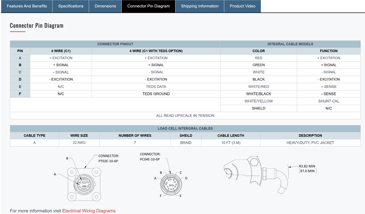
1000 Series Connector Pin Diagram

Essential Electrical Wiring Support Guide

Interface provides a detailed electrical wiring support reference with cable and connector wire color coding diagrams. The thorough online resource is a must-have for anyone who needs a quick reference to the color configurations. Download a copy here.

Interface Electrical Wiring Diagrams Resource includes:

  • Electrical Selection Chart by Model Number
  • Load Cell Cable Wiring Diagram
  • Load Cell Connector Wiring Diagram
  • Load Cell Wire Color Coding
  • Torque Transducer Wire Color Coding
  • 3-Axis Wire Color Coding
  • 3-Axis Round Wire Color Coding
  • 6-Axis Wire Color Coding

The Importance of Consistent Color Coding

While there are standard conventions, it is critical to always consult the specific load cell’s datasheet. Adherence to standards reduces errors and simplifies troubleshooting, especially in complex setups. Proper color coding drastically reduces the time spent troubleshooting connection issues.

Understanding Wire Systems

The four wires in a typical load cell are related to a Wheatstone bridge circuit.

  • Excitation (+/-): The voltage supplied to the bridge.
  • Signal (+/-): The millivolt output is proportional to the force applied.

Many cables are also shielded to reduce noise. The shield wire, often bare or in a separate color, is typically grounded.

Six-wire systems add two “sense” or “remote sense” wires. These wires compensate for voltage drops in the excitation wires, improving accuracy. They are connected back to the instrumentation to provide feedback on the actual voltage at the bridge.

Multi-axis sensors are inherently complex, and accurate wiring is essential. Each axis has its own set of excitation and signal wires. Always refer to Interface’s online pin diagrams and our electrical reference.

Nine Practical Wiring Tips

1 – Always double-check all connections before applying power.

2 – Ensure proper color matching by reviewing the pinouts in your specifications.

3 – Check if you have acceptable input to data acquisition.

4 – Examine noise immunity and requirements for shielded cables.

5 – Use an appropriate cable length as the effect of long cable lengths on signal integrity.

6 – Determine proper grounding.

7 – Use appropriate crimping tools and connectors for reliable connections.

8 – If the load cell is in a harsh environment, use cables and connectors rated for that environment.

9 – The load cell may need to be recalibrated after wiring changes.

Common problem areas are loose or dirty electrical connections or incorrect connections of color-coded wires.

Expert Advice Related to Wiring, Cables, and Connectors

Interface partners with Rob Fuge, CEO and founder of Epsilon Laboratory, a strain gage, load cell, and cable expert. He provides tremendously useful references and support in Minimizing Error in Load Cell Cables.

“If you add length to the cable by extending the lead wires without taking the proper steps to correct it, you will see a decreased signal. This is because the voltage drop between the DAQ and the load cell is increased due to the added resistance of the lead wires.” – Rob Fuge

Rob offers this respected tip: check the number of pins. Loading cells with integral cable terminated to a connector is extremely important. Rob’s suggestions:

Pins Tip #1—If there are 4 pins, your load cell does not have sense leads. They can be added to the mating connector and extension cable without altering the calibration, but cable temperature effects will persist in the 4-conductor portion.

Pins Tip #2 – If there are 6 pins, your load cell may have sense leads. Consult the data sheet for the assignment of each pin and see if any pin pairs have much lower resistance than the rest. By way of example, if pins 1 and 3 measure 350 ohms, but pins 1 and 6 measure 1.2 ohms, then either pin 1 or 6 is likely the intended sense lead. Once you have confirmed that your load cell has sense leads, you can extend all 6 conductors via a mating cable. Any time a solder joint is reflowed, it may slightly impact the calibration. Ask a load cell expert for help designing your measurement for the highest possible accuracy.

Get more insights and load cell instrument-specific cable references from Epsilon Laboratory’s Rob Fuge here.

Cable Assemblies and Connectors

The Interface Sensor Interconnect Cable Assemblies Guide provides wire information for connecting transducers to Interface indicators and other instrumentation.

A cable assembly transmits signals and ensures accurate measurements. Features like shielding to protect against interference, twisted pairs to reduce noise, and durable jackets to withstand environmental factors are important considerations.

Utilize the Interface Cables and Connectors Brochure when pairing a sensor with an instrument, whether using an Interface instrumentation device or another product you use to gather and analyze data. You will get a full review of cable assemblies, connectors, and electrical details, including load cell integration cables type, wire size, number of wires, shield, description, load cell cable wiring diagrams, and connectors.

Cable Effects on Performance from Interface’s Load Cell Field Guide

Cable Length Effects: If the Interface load cell is sold with cables of any length, the sensitivity is determined by the installed cable during calibration. For load cells with connectors, there will be a loss of sensitivity of approximately 0.37% per 10 feet of 28 gage cable and 0.09% per 10 feet of 22 gage cable. This error can be eliminated if a six-wire cable is run to the end of the load cell cable or connector and used with an indicator with sense lead capability.

Temperature Effects: Since cable resistance is a function of temperature, the cable’s response to temperature change affects the thermal span characteristics of the load cell cable system. For 6-wire systems, this effect is eliminated. For 4-wire cables, the effect is compensated for in the standard cable lengths offered with the load cells if the load cell and cable are at the same temperature simultaneously. For non-standard cable lengths, there will be an effect on thermal span performance. The impact of adding 10 feet of 28 gage cable is to cause a decrease in sensitivity with a temperature equal to 0.0008%/°F (an amount equal to the standard Interface specification).

Adding 10 feet of 22 gage cable decreases the sensitivity by 0.0002%/°F. Customers can often tolerate the degraded performance since our standard specification is extremely tight. However, this can be a significant factor for long cable runs or high-accuracy applications. In such cases, the best approach to the problem is to run six wires to the end of the standard cable length and sense the excitation voltage, eliminating the problem. For a copy of Interface’s essential Load Cell Field Guide, go here.

Understanding load cell wiring is paramount for accurate and reliable force measurement. Correct connections ensure the signal transmitted from the strain gauge through the cabling to the instrumentation is precise and error-free. Incorrect wiring can lead to inaccurate data, equipment damage, and safety hazards.

By adhering to specifications and understanding colors, connectors, and cables, load cell users can minimize errors, streamline troubleshooting, and maximize the performance and longevity of their load cell systems. A thorough grasp of load cell wiring is essential for obtaining trustworthy and consistent measurement results.

Electrical_Wiring_Diagram
Tags: 101 Load Cell Wiring, 101 Series, 4-wire, 6-wire, cable assembly, cable effects, cable length, connectors, DAQ, data acquisition system, Did You Know, digital signal, electrical, engineering, error, instrumentation, IQ Blog, IQBlog, IQBlog IQ Blog, load cell, Load Cell Basics, Load Cell Field Guide, Load Cells, load pin, mating connectors, multi-axis sensor, pinout, pins, Rob Fuge, signal, specifications, strain gage, temperature effects, Wheatstone bridge, wire colors, wiring
Share this entry
  • Share on Facebook
  • Share on X
  • Share on Pinterest
  • Share on LinkedIn
  • Share on Reddit
  • Share by Mail
https://staging.interfaceforce.com/wp-content/uploads/INTERFACE-101-Wiring.jpg 800 800 Jamie Glass /wp-content/uploads/Interface_White_Red.svg Jamie Glass2025-03-11 08:08:522025-04-07 10:06:36Load Cell Wiring 101
You might also like
LOAD CELLS 101 Load Cell 101 and What You Need to Know
Shear And Bending The Basics of Shear and Bending Beams
Teamwork 1 The Power of Teamwork Drives Interface Success
Custom Solutions 1 1 Interface Goes Above and Beyond with Custom Solutions
55k Automated Calibtration System 1 Present and Future Interface Calibration Product Family
AEROSPACE Interface 1 Taking Flight with Interface

SUBSCRIBE TO THE INTERFACEIQ BLOG

  • Remember to subscribe to Interface’s IQ Blog. It’s a must-read for anyone looking to stay informed and up-to-date on the world of load cells with expert insights, engaging content, and a fresh perspective.

Latest Posts

  • Technical Validation of Water Safety Equipment Across Maritime ApplicationsAugust 13, 2026 - 8:08 am
  • Complex Testing 6 Axis Bx8 DAQ
    Complex Testing with 6-Axis Load Cells and BX8 DAQ InstrumentationAugust 11, 2026 - 8:08 am
  • Moment 101
    Moment 101August 6, 2026 - 8:08 am
  • Rigging
    The Mechanics of Suspended Loads in Heavy RiggingAugust 4, 2026 - 8:08 am
  • INTERFACE TECH TALK Single Load Cell Platform Weighing
    Why Use a Single Load Cell for Platform Weighing?July 30, 2026 - 8:08 am

Explore our Products

  • Accessories
  • Calibration Equipment
  • Digital Instrumentation
  • G-Series
  • Hazardous Locations
  • Instrumentation
  • Load Button Load Cells
  • Load Cell Simulators
  • Load Cells
  • Load Pins, Tension Load Links, and Load Shackles
  • Mini Load Cells
  • Multi-Axis Sensors
  • Quickship
  • Torque Transducers
  • Wireless

All Products

  • Load Cells
  • Interface Mini
  • Load Button Load Cells
  • Multi-Axis Sensors
  • Torque Transducers
  • Load Pins, Tension Links, and Load Shackles
  • Instrumentation
  • Digital Instrumentation
  • Wireless Telemetry System
  • Bluetooth® Telemetry System
  • Intrinsically Safe
  • Calibration Systems
  • Accessories
  • G-Series

Contact Us

  • Feedback
  • Customer Support
  • Contact Form
  • Career Opportunities
  • Certifications and Compliance
  • Locate A Rep or Distributor

Solutions

  • ForceEDU
  • Custom Solutions
  • Industry Solutions
  • Application Notes
  • Animated Application Notes
  • Case Studies
  • White Papers
  • Interface Training Videos

Services

  • Calibration and Repair Request
  • Load Cell Troubleshooting
  • Software and Drivers
  • Technical Library

News

  • Events
  • Newsletter
  • Interface IQ Blog
  • InterfaceIQ Podcast
ISO 17025 Scope Accreditation
© Copyright - Interface - powered by Enfold WordPress Theme
  • Warranty And Repair Policy
  • Privacy Policy
  • Certifications and Compliance
Link to: The Force Behind the Future of Humanoid Robotics Link to: The Force Behind the Future of Humanoid Robotics The Force Behind the Future of Humanoid RoboticsHumanoid Link to: Force Measurement Expands Environmental Testing Capabilities Link to: Force Measurement Expands Environmental Testing Capabilities Environmental TestingForce Measurement Expands Environmental Testing Capabilities
Scroll to top Scroll to top Scroll to top

We use cookies to enhance your browsing experience, serve personalized content, and analyze our traffic. By clicking "Accept All Cookies", you consent to our use of cookies.

Accept All CookiesReject AllCookie Settings

Cookie and Privacy Settings


How we use cookies

How we use cookies

We may request cookies to be set on your device. We use cookies to let us know when you visit our websites, how you interact with us, to enrich your user experience, and to customize your relationship with our website.

Click on the different category headings to find out more. You can also change some of your preferences. Note that blocking some types of cookies may impact your experience on our websites and the services we are able to offer.

Essential Website Cookies

Essential Website Cookies

These cookies are strictly necessary to provide you with services available through our website and to use some of its features.

Because these cookies are strictly necessary to deliver the website, you cannot refuse them without impacting how our site functions. You can block or delete them by changing your browser settings and force blocking all cookies on this website.

Google Analytics Cookies

Google Analytics Cookies

These cookies collect information that is used either in aggregate form to help us understand how our website is being used or how effective our marketing campaigns are, or to help us customize our website and application for you in order to enhance your experience.

If you do not want us to track your visit to our site, you can disable tracking in your browser here:

Other external services

Other external services

We also use different external services like Google Webfonts, Google Maps and external Video providers. Since these providers may collect personal data like your IP address we allow you to block them here. Please be aware that this might heavily reduce the functionality and appearance of our site. Changes will take effect once you reload the page.

Google Webfont Settings:

Google Map Settings:

Privacy Policy

Privacy Policy

I agree to the terms and conditions laid out in the Privacy Policy

Update Your SettingsDo not accept and hide notification
Open Message Bar Open Message Bar Open Message Bar

Please share your location to continue.

Check our help guide for more info.

share your location