Features and Benefits
- ASCII serial output
- Serial output to printer, display, PC or PLC
- Simple configuration and calibration
- Wireless range of up to 800 m (up to 2,625 ft)
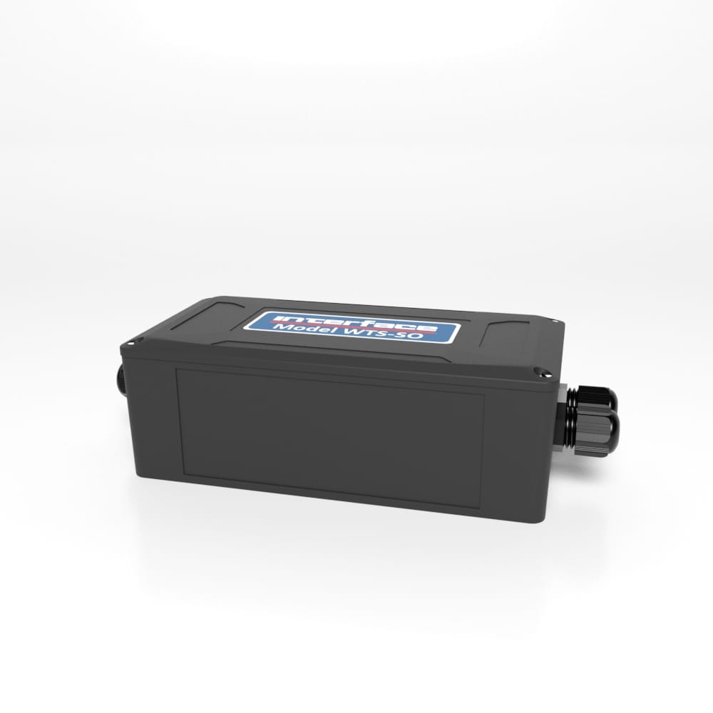
WTS-SO Wireless Interface with ASCII Serial Output
The pricing listed on our website is only for U.S. buyers and all pricing is subject to change without notice. Any inquiries for products from buyers outside of the U.S. will receive a quote and availability from the licensed distributor nearest your region. These prices will be based on product availability, currency conversions, markets, taxes, shipping costs, as well as local support.

WTS-SO Wireless with ASCII Serial Output has a user defined ASCII report that can contain live values and sum of up to eight WTS transmitters and forms part of the WTS modular telemetry system.
The data sent by transmitter modules can be utilized by multiple receivers such as displays, handheld readers, analog outputs, relay modules and computer interfaces. Receivers support common industrial power supplies and are available in robust IP rated enclosures with internal antennas optimized to give outstanding coverage.
The WTS-SO supports RS232 and RS485 connectivity.
The WTS Toolkit software offers a fast and simple way to configure the report format and to choose the associated transmitter modules. The reports could be just a single line giving a value to be fed into a serial display, for example, or could be a multi-line report for delivery to a printer.
WTS-SO Wireless with ASCII Serial Output has a user defined ASCII report that can contain live values and sum of up to eight WTS transmitters and forms part of the WTS modular telemetry system.
The data sent by transmitter modules can be utilized by multiple receivers such as displays, handheld readers, analog outputs, relay modules and computer interfaces. Receivers support common industrial power supplies and are available in robust IP rated enclosures with internal antennas optimized to give outstanding coverage.
The WTS-SO supports RS232 and RS485 connectivity.
The WTS Toolkit software offers a fast and simple way to configure the report format and to choose the associated transmitter modules. The reports could be just a single line giving a value to be fed into a serial display, for example, or could be a multi-line report for delivery to a printer.
U.S. dimensions and capacities are provided for conversion only. Standard products have International System of Units (SI) capacities and dimensions.
U.S. dimensions and capacities are provided for conversion only. Standard products have International System of Units (SI) capacities and dimensions.
You will need to connect power and serial to the WTS-SO for it to operate. Only power is required on J4 to enable configuration using a base station and the appropriate toolkit software.
The serial output is set at 8 data bits, 1 stop bit and no parity. The baud rate can be selected as can RS232 or RS485 operation.
Switch positions 1 to 4 are not used and can be in any position.
Switch positions 5 to 7 control the baud rate for the serial interface.
| Baud Rate / USB | 5 | 6 | 7 |
| NA | Off | Off | Off |
| 9600 | On | Off | Off |
| 19200 | Off | On | Off |
| 38400 | On | On | Off |
| 57600 | Off | Off | On |
| 115200 | On | Off | On |
| 230400 | Off | On | On |
| 460800 | On | On | On |
This switch position selects whether the serial interface is RS232 or RS485.
| 232/485 | 8 |
| RS232 | Off |
| RS485 | On |
The RS232 interface uses TX, RX and GND to connect to a PC, PLC etc. and uses standard RS232 voltage levels.
The baud rate can be selected by setting the DIP switches stated above.
The WTS-GW1 will require power cycling to utilise a baud rate change.
| PC 9 Way D Plug Pin | Signal Direction | Signal | Base Station Connection |
| 3 (TX) | _> | RX | J6 RX or J7 Pin 3 |
| 2 (RX) | <_ | TX | J6 TX or J7 Pin 2 |
| 5 (Gnd) | GND | J6 GND or J7 Pin 5 | |
| 8 (CTS) | <_ | CTS | J6 CTS or J7 Pin 8 |
The RS485 interface (This is a 2 wire 485 interface and will not work with 4 wire 485 buses) uses TX, RX and GND to connect to a PC, PLC etc. and uses standard RS485 voltage levels.
The baud rate can be selected by setting the DIP switches stated above.
The WTS-GW1 will require power cycling to utilise a baud rate change.
Depending on the RS485 interface or hardware the connections vary and are not standard therefore we can only show the connections to the WTS-GW1. You must refer to the user manual regarding your RS485 connection to ascertain the correct connections.
| PC / PLC Connection | Signal | Base Station Connection |
| Refer to RS485 Device User Manual | A | J4 -A |
| Refer to RS485 Device User Manual | B | J4 +B |
| Refer to RS485 Device User Manual | GND | J4 SH |
When using RS232 or RS485 you should use the fastest baud rate possible. At lower rates data can be lost because it can arrive from the radio faster than the gateway station can send it serially.
For more information visit Electrical Wiring Diagrams
| Dimensions | 6.46 × 3.31 × 2.24 in |
|---|
U.S. dimensions and capacities are provided for conversion only. Standard products have International System of Units (SI) capacities and dimensions.
U.S. dimensions and capacities are provided for conversion only. Standard products have International System of Units (SI) capacities and dimensions.
You will need to connect power and serial to the WTS-SO for it to operate. Only power is required on J4 to enable configuration using a base station and the appropriate toolkit software.
The serial output is set at 8 data bits, 1 stop bit and no parity. The baud rate can be selected as can RS232 or RS485 operation.
Switch positions 1 to 4 are not used and can be in any position.
Switch positions 5 to 7 control the baud rate for the serial interface.
| Baud Rate / USB | 5 | 6 | 7 |
| NA | Off | Off | Off |
| 9600 | On | Off | Off |
| 19200 | Off | On | Off |
| 38400 | On | On | Off |
| 57600 | Off | Off | On |
| 115200 | On | Off | On |
| 230400 | Off | On | On |
| 460800 | On | On | On |
This switch position selects whether the serial interface is RS232 or RS485.
| 232/485 | 8 |
| RS232 | Off |
| RS485 | On |
The RS232 interface uses TX, RX and GND to connect to a PC, PLC etc. and uses standard RS232 voltage levels.
The baud rate can be selected by setting the DIP switches stated above.
The WTS-GW1 will require power cycling to utilise a baud rate change.
| PC 9 Way D Plug Pin | Signal Direction | Signal | Base Station Connection |
| 3 (TX) | _> | RX | J6 RX or J7 Pin 3 |
| 2 (RX) | <_ | TX | J6 TX or J7 Pin 2 |
| 5 (Gnd) | GND | J6 GND or J7 Pin 5 | |
| 8 (CTS) | <_ | CTS | J6 CTS or J7 Pin 8 |
The RS485 interface (This is a 2 wire 485 interface and will not work with 4 wire 485 buses) uses TX, RX and GND to connect to a PC, PLC etc. and uses standard RS485 voltage levels.
The baud rate can be selected by setting the DIP switches stated above.
The WTS-GW1 will require power cycling to utilise a baud rate change.
Depending on the RS485 interface or hardware the connections vary and are not standard therefore we can only show the connections to the WTS-GW1. You must refer to the user manual regarding your RS485 connection to ascertain the correct connections.
| PC / PLC Connection | Signal | Base Station Connection |
| Refer to RS485 Device User Manual | A | J4 -A |
| Refer to RS485 Device User Manual | B | J4 +B |
| Refer to RS485 Device User Manual | GND | J4 SH |
When using RS232 or RS485 you should use the fastest baud rate possible. At lower rates data can be lost because it can arrive from the radio faster than the gateway station can send it serially.
For more information visit Electrical Wiring Diagrams
| Dimensions | 6.46 × 3.31 × 2.24 in |
|---|


 WTSLP Wireless Custom Stainless Steel Load Pin


