Features and Benefits
- Provides limit switching
- Two relays mains rated
- Accepts up to 16 devices
- Provides a range of relay operation modes
- Loss of signal alarm relay
- Latch and inversion options for all relays
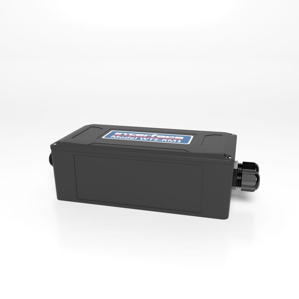
WTS-RM1 Wireless Relay Output Receiver Module
The pricing listed on our website is only for U.S. buyers and all pricing is subject to change without notice. Any inquiries for products from buyers outside of the U.S. will receive a quote and availability from the licensed distributor nearest your region. These prices will be based on product availability, currency conversions, markets, taxes, shipping costs, as well as local support.

Wireless Relay Output Receiver Module acts on data from any of the WTS wireless transmitter modules and can be used for alarm and control purposes forming part of the WTS modular telemetry system.
The data sent by transmitter modules can be utilized by multiple receivers such as displays, handheld readers, analog outputs, relay modules and computer interfaces. Receivers support common industrial power supplies and are available in robust IP rated enclosures with internal antennas optimized to give outstanding coverage.
The WTS-RM1 offers two single pole changeover relays with mains rated 5 amp contacts for power switching. Functionality includes set-points, inversion, latching and hysteresis. The WTS Toolkit offers a fast and simple way to configure the relays operation and set-point values, which are entered in the engineering units of the associated transmitter modules.
Wireless Relay Output Receiver Module acts on data from any of the WTS wireless transmitter modules and can be used for alarm and control purposes forming part of the WTS modular telemetry system.
The data sent by transmitter modules can be utilized by multiple receivers such as displays, handheld readers, analog outputs, relay modules and computer interfaces. Receivers support common industrial power supplies and are available in robust IP rated enclosures with internal antennas optimized to give outstanding coverage.
The WTS-RM1 offers two single pole changeover relays with mains rated 5 amp contacts for power switching. Functionality includes set-points, inversion, latching and hysteresis. The WTS Toolkit offers a fast and simple way to configure the relays operation and set-point values, which are entered in the engineering units of the associated transmitter modules.
U.S. dimensions and capacities are provided for conversion only. Standard products have International System of Units (SI) capacities and dimensions.
U.S. dimensions and capacities are provided for conversion only. Standard products have International System of Units (SI) capacities and dimensions.
You will need to connect power to the WTS-RM1 for it to operate. Only power is required to enable configuration using a base station and the appropriate toolkit software.
Power is connected to the two part two way screw terminal connector as shown in the diagram below.
| Mode | Flashes 2 x per second when operational |
| Activity | Flashes when WTS data packets are received |
| Time Out | No WTS data present for longer than user defined period |
| Error | Remote WTS error from any defined WTS input module |
| Relay 1 | Relay 1 Energized (Connection between COM and NO) |
| Relay 2 | Relay 2 Energized (Connection between COM and NO) |
Digital Input 1 Can either reset a latched relay 1 or transmit a Data Provider Packet of a specified
Data Tag
Digital Input 2 Can either reset a latched relay 2 or transmit a Data Provider Packet of a specified
Data Tag
Digital Input 3 Resets both latched relays
The WTS-RM1 can accept 8 WTS data inputs for each of the two relays, the total of the inputs compared to the set point and mode of the relay channel affects whether the relay is energized or not. In addition when considering the use relays attention should be paid as to what state the system will be in when the power is off. The diagram below outlines how wiring and normal and inverse modes influence the state of relays.
(COM = Common, NO = Normally Open, NC = Normally Closed)
The WTS-RM1 also features a third Alarm relay. The Alarm relay is energized from start up, (connection made between COM and NC). The relay de-energizes if an error is detected, an error is classed as a timeout and optionally can include Integrity error or low Battery. The Alarm Relay will return to normal (energized) once the source of the error is removed.
For more information visit Electrical Wiring Diagrams
| Dimensions | 6.50 × 3.30 × 2.20 in |
|---|
U.S. dimensions and capacities are provided for conversion only. Standard products have International System of Units (SI) capacities and dimensions.
U.S. dimensions and capacities are provided for conversion only. Standard products have International System of Units (SI) capacities and dimensions.
You will need to connect power to the WTS-RM1 for it to operate. Only power is required to enable configuration using a base station and the appropriate toolkit software.
Power is connected to the two part two way screw terminal connector as shown in the diagram below.
| Mode | Flashes 2 x per second when operational |
| Activity | Flashes when WTS data packets are received |
| Time Out | No WTS data present for longer than user defined period |
| Error | Remote WTS error from any defined WTS input module |
| Relay 1 | Relay 1 Energized (Connection between COM and NO) |
| Relay 2 | Relay 2 Energized (Connection between COM and NO) |
Digital Input 1 Can either reset a latched relay 1 or transmit a Data Provider Packet of a specified
Data Tag
Digital Input 2 Can either reset a latched relay 2 or transmit a Data Provider Packet of a specified
Data Tag
Digital Input 3 Resets both latched relays
The WTS-RM1 can accept 8 WTS data inputs for each of the two relays, the total of the inputs compared to the set point and mode of the relay channel affects whether the relay is energized or not. In addition when considering the use relays attention should be paid as to what state the system will be in when the power is off. The diagram below outlines how wiring and normal and inverse modes influence the state of relays.
(COM = Common, NO = Normally Open, NC = Normally Closed)
The WTS-RM1 also features a third Alarm relay. The Alarm relay is energized from start up, (connection made between COM and NC). The relay de-energizes if an error is detected, an error is classed as a timeout and optionally can include Integrity error or low Battery. The Alarm Relay will return to normal (energized) once the source of the error is removed.
For more information visit Electrical Wiring Diagrams
| Dimensions | 6.50 × 3.30 × 2.20 in |
|---|


 WTS-SO Wireless Interface with ASCII Serial Output


